BELT CONVEYORS - DESIGN, OPERATION
AND OPTIMIZATION
CONVEYOR DESIGN AND DESIGN STANDARDS
P. Staples Pr.Eng BSc. MSAIME
Managing Director
Conveyor Knowledge and Information Technology (Pty)Ltd (CKIT)
INDEX
- INTRODUCTION
- JUSTIFICATION FOR A STANDARD
- PRESENT DESIGN STANDARDS
- PROPOSED STANDARD FORMAT
4.1 Power and Tension
4.2 Pulley and Shafts
4.3 Selection of Belt Width and Velocity
4.4 Idler Standards
4.5 Drive Standards
- CONCLUSION
SUMMARY
This paper has been prepared with the intention of highlighting the problems
faced by design engineers who are forced to undertake the design of belt conveyor systems using
a multitude of design standards which have not been brought into line with modern technological
advancements.
To overcome some of these problems, a basic outline of a universal standard has
been proposed, which can easily be adapted to suit individual needs, without reducing the efficiency
of the designer and his team.
1. INTRODUCTION
The design of belt conveyor systems has been one of the most common occurrences
in the South African mining field for over one hundred years. Conveyors are seen on virtually
all mining installations,
and are the biggest problem for the plant maintenance engineer, being the cause of most plant
shutdowns.
Why do belt conveyors cause such problems? It must be remembered that mining
houses usually have a set of design standards to conform to; standards which are claimed have
been developed over many years to suit their own needs in the materials handling field.
However, as I can understand the need for some aspects of a standard, others
completely baffle me. It appears that having spent a great deal of time over certain requirements
of a design standard, many of the fundamentals to which I am referring are of course the effects
of overpowering on the whole conveyor system. Also, we know that to convey material from one point
to another requires a specific amount
of power using a belt designed to withstand a definite tension, so
why is it that if a conveyor design problem is set to a number of designers, they will
come up with many variations on a solution, even using the same design specification.
This of course comes down to the interpretation of, and the familiarity with the
standard to be used. Basically I am suggesting that the standards as available to-day, leave a
lot to be desired from the point of view of completeness, and ease of application.
2. JUSTIFICATION FOR A STANDARD
Do we need a standard at all? and if so, what form should it take?
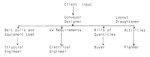
To answer this question let us look at a typical design office set up. On any project there
are three key categories of staff, the designers, his draughtsmen and a group of peripheral
staff, (planners, buyers, structural, civil and electrical engineers). Thus we have a set up
which looks as follows:-
Figure 1. Typical project Engineering Flow Sheets
The designer is given a basic specification which will include material
type and quantity to be conveyed from A to B. This he must transform into drawings for manufacture
and fabrication, design data for civil, electrical
and structural engineers, bills of quantities for buyers and activity networks for planners.
With the exception of the planning information which is only really relevant for the construction
phase of the project, the designer has
a problem which he will find very difficult to overcome, and that is to supply all the necessary
information to each discipline on the project when they require it.
Therefore having obtained a scope of work from the client in question,
the designer has to quickly produce the design data, but before he is able
to proceed he must obtain information from his drawing office relating to the layout of the
conveyors in the system. Now the problems begin: Prior to undertaking any calculations
whatsoever the designer must check the specifications to which he must conform.
As virtually all clients have their own opinion on the subject of conveyor
design, we can rest assured there will be some form of client input, whether
it be a two volume manuscript or simply an, 'All drives shall ........' document.
The designer is confronted with conforming to the said specification, but
much worse, he must ensure that his drawing office staff are aware that there
is a specification to work to. Consider that the previous week they may have been working
on another project and had to conform to a completely different specification.
What does the designer do? Does he circulate multiple copies to his
drawing office with the instruction that it must be read prior to any work being started.
If so, he will possibly not meet his deadline on the supply of data to the peripheral
disciplines.
Does he try to check that his draughtsmen conform by 'looking over their
shoulders' from time to time (which is the way mistakes are guaranteed to occur). Alternatively
does he instruct his drawing office that there is a specification to work to and that it is lying
around somewhere and to 'please check it if you are not to sure of how to proceed'.
In all the offices in which I have worked, the last two solutions have been
applied, with the result that, almost without exception, the experienced draughtsmen who know
how to make a system work will continue with very little reference to the said
specification.
The problem may be that on this project 'the pulleys are much bigger,
the take-up length must be selected using an ill defined formula and basically
we don't know how to design a conveyor anymore. If this problem is caught
early enough we only have to change a quantity of drawings and are then back
on the right road. However you can be sure that in practice it will be too late, and the
designer has to go to the client and ask for a concession because he is not able to conform to
the specification, and to make any changes to
the drawings now will put him way behind schedule. Furthermore before the client will accept
deviations to the proposed format, every avenue must be explored, and a report on the deviation
prepared.
The designer is now behind whether he likes it or not and to make up time he
must neglect the one function which completes the total conveyor design, that
of secondary design. By secondary design, I mean the design which comes after the conceptual
or general arrangement layouts are complete. This is the design of the chutes, the location
of bearings, the belt cleaning system to be
employed and the access for maintenance. This is left to a draughtsman without any engineering
support. However, the secondary design usually encompasses
the major problems of belt conveyor system design. These are areas with very little coverage in
specifications, with comments such as, 'all conveyors will have pulleys at terminal
points', being the limit to such specifications.
I pose the question again, do we need a design standard? Those who agree with
the scenario I have set will probably say, 'Allow the designer the freedom to do the job'.
However 1 feel that a standard is
essential. There are very few specialist conveyor designers and thus some form of
guidance must be given. However there should be only one standard, with one basic set of
parameters and which can cater for the needs of every mining and process plant application.
Without lessening the efficiency of the designer and his team such a standard will facilitate
the efficiency
the overcoming of the problems occurring in secondary design.
We know this has been tried repeatedly in the past, but always in isolation
from the main stream of design and usually with the statement, 'but it caters for our own
individual needs', as justification.
Having been confronted with conveyor design standards for a number of years,
I have still to find a true specialist need, I know that some clients require less capacity
on a belt, others require larger pulleys and thicker belts, requiring the use of complicated
formula to arrive at a solution, but this
can not be justification for devising completely individual specifications, which could more
suitably be covered in a single paragraph of a comprehensive specification.
3. PRESENT DESIGN STANDARDS
Let us look at at the Conveyor design standards available, and in particular
the four most commonly used, C.E.M.A., GOOD YEAR, ISCOR and A.A.C. If we consider the power and
tension variation predicted by using these systems, as in Table 1, we see quite a wide range of
possibilities. The reason for this is in the selection of the rolling resistance factor,
(coefficient of friction, resistance to flexure or other commonly used terms) which varies
between 0,016 and 0,035 as used in the above standards.
Table 1 Power and Tension
calculations.
1(a) based on belt capacity of 500tons per hour, belt width of 900mm and a
belt
velocity of 2,2m/sec.
Length |
Lift |
C.E.M.A. |
GOOD YEAR |
ISCOR |
A.A.C. |
| |
|
Power |
Tesn |
Power |
Tesn |
Power |
Tesn |
Power |
Tesn |
m |
m |
kW |
kN |
kW |
kN |
kW |
kN |
kW |
kN |
30 |
0 |
6 |
9 |
15 |
16 |
16 |
19 |
12 |
18 |
200 |
60 |
101 |
65 |
99 |
64 |
104 |
66 |
102 |
66 |
1000 |
0 |
81 |
40 |
89 |
43 |
113 |
54 |
104 |
50 |
1000 |
40 |
132 |
72 |
143 |
77 |
167 |
88 |
158 |
84 |
1(b) based on belt capacity of 2000tons per hour, belt width of 1500mm
and a belt
velocity of 3m/sec.
Length |
Lift |
C.E.M.A. |
GOOD YEAR |
ISCOR |
A.A.C. |
| |
|
Power |
Tesn |
Power |
Tesn |
Power |
Tesn |
Power |
Tesn |
m |
m |
kW |
kN |
kW |
kN |
kW |
kN |
kW |
kN |
30 |
0 |
18 |
22 |
36 |
41 |
38 |
42 |
37 |
42 |
200 |
60 |
378 |
167 |
380 |
168 |
403 |
176 |
391 |
172 |
1000 |
0 |
221 |
84 |
262 |
98 |
349 |
127 |
315 |
116 |
1000 |
40 |
439 |
174 |
479 |
188 |
567 |
217 |
533 |
206 |
On the shorter systems this difference is quite insignificant, except that the
belt length factor plays an important part. However on the now common large overland type systems,
these variations are unsatisfactory to say the least.
Are we able or prepared to accept such variations? Able, I will say yes,
provided we take cognisance of the effects of overpowering. However I am not convinced we
should be prepared to accept these variations, apart from the overpowering factor there
are purely economic considerations to account for. This point is very noticeable when one
becomes involved in economic evaluations (feasibility studies) of various alternative
solutions to a specific materials handling problem. For instance, how competitive would
a pneumatic conveying system or cable belt system be if designed to
similar sets of standards as the conveyor. However as these standards are as yet,
not available, the manufacturer of competitive systems has far reaching advantages over the
conveyor manufacturers.
I am not for one moment suggesting that the competitive systems are under
designed, simply that the designer is not limited to designing within a conservative
specification.
Too often we see examples of conveyor systems feeding process plants,
where to conform to specification the whole conveyor network is designed for a large
amount of excess capacity. However, this philosophy is not transferred to the related
equipment in the rest of the plant.
4. PROPOSED STANDARD FORMAT
4.1 Power and Tension
With power and tension calculations there exists the possibility for
a combination of all four of the above standards by utilizing a single friction factor for the
shorter belts, but eliminating the belt length factor which can easily be compensated for with
the overrating factor
of the motor. In progressing to the longer conveyors this factor could be variable, as advocated
by C.E.M.A., only now be simply a function
of belt length and capacity. Then we could use a simplified formula
as follows:-
Power (kW) = |
9.81 |
x L.V((kX+kY(Wm+Wb)+,015Wb)+
(H.Wm)) |
1000 |
Where
- L = Horizontal pulley centers (m)
- H = Vertical pulley centers (m)
- V = Belt velocity (m/sec.)
- Wm = Mass of material per meter run (kg)
- Wb = Mass of belt per metre run (kg)
- 0,015 = Return belt resistance
- kX = Belt slide and Idler rotational resistance and can be obtained from:-
kX = 0,00068(Wm+Wb)+0,022(rotating mass of the Idler per meter) (kg/m)
- kY = Resistance of the belt of flexure as it
moves over the Idlers, and can be considered to
be the same as the friction factors given in
all the specifications.
Typical values of kY are given in table 2 below.
Table 2. Selection of kY factor based on Belt
length, lift and capacity.
Length |
Lift |
kY |
kY |
kY |
kY |
m |
m |
500t/hr. |
1000t/hr. |
2000t/hr. |
3000t/hr. |
100 |
20 |
0,035 |
0,030 |
0,026 |
0,022 |
200 |
20 |
0,032 |
0,026 |
0,022 |
0,020 |
200 |
40 |
0,030 |
0,022 |
0,020 |
0,020 |
400 |
20 |
0,030 |
0,022 |
0,020 |
0,020 |
400 |
40 |
0,026 |
0,020 |
0,020 |
0,020 |
800 |
40 |
0,022 |
0,020 |
0,020 |
0,020 |
1000 |
40 |
0,020 |
0,020 |
0,020 |
0,020 |
To enable the client to maintain control of the outcome of the calculation,
it is necessary only to specify the kY factor to be used in a simple addendum to the main
specification.
Belt tension calculation can be kept straightforward, provided the designer
starts by considering the minimum belt tensions, at both the drive and tail pulleys,
by using the following formulae :-
Tmin = 4,2x9,81/1000 si(Wb+Wm) kN
Where 4,2 = Factor based on a 3% belt sag.
Si
= Idler spacing,m
and
Tslack side = Teffective / e -1
Where T effective is the installed drive effective tension and not the effective
tension computed from the above power formula.
The one problem that is encountered is in the selection of a coefficient of
friction for the drive pulley. A standard such as given In Table 3 could
be used.
Table 3 Coefficient of Friction
for Drive Pulleys.
| |
|
Type of Take Up |
Plant
Description |
Conveyor
Construction |
Automatic |
Manual |
Lagged |
Unlagged |
Lagged |
Unlagged |
Wet |
Covered
Uncovered |
0,25
0,20 |
0,10
0,10 |
0,20
0,20 |
0,10
0,10 |
Semi-wet |
Covered
Uncovered |
0,30
0,25 |
0,20
0,15 |
0,25
0,22 |
0,18
0,13 |
Dry |
Covered
Uncovered |
0,35
0,30 |
0,22
0,18 |
0,25
0,25 |
0,20
0,15 |
Table 3 has been compiled from empirical data such as that given in Table 4.
It should be noted that these values are the limiting conditions (when the belt is on the point
of slipping). The actual coefficients of friction developed between surfaces are, in
practically all cases where slipping does not occur, in excess of those listed.
Therefore, the convention of using these values does not reflect what actually
occurs at the drive pulley.
If one considers a drive pulley under operating conditions then the higher
tensioned belt section is stretched more than on the lower tensioned section, thus the
belt entering the positive drive will be traveling faster than when it leaves it. The elastic
recovery of the belt occurs over only a part of
the total angle of contact, and it is at this point, where creep takes place,
that the driving is done, while making full use of the coefficient of friction.
By applying the classic tension formula to the whole angle of wrap
a fictitious coefficient of friction is being used
Table 4. Recommended Drive Coefficient of
Friction of Various Standards.
Condition
|
C.E.M.A.
|
STEVENS
ADAMSON |
BRIDGESTONE
|
LINATEX
|
REMA
TIP TOP |
Bare pulley |
0,25 |
0,35 |
0,20 |
--- |
--- |
Lagged |
0,35 |
0,35 |
--- |
0,60 |
0,45 |
Dry Lagged |
0,35 |
0,35 |
0,35 |
0,60 |
0,45 |
Wet Lagged |
0,35 |
0,35 |
0,25 |
0,80 |
0,35 |
Wet & Dirty |
0,35 |
0,35 |
0,20 |
0,40 |
0,25 |
The advantage of working from minimum drive tension back to the maximum
drive tension, can be better explained if one looks at the design of pulleys and shafts.
Over the years there has been a lot written about the design of a pulley shaft, with the
aim of trying to eliminate the high failure rate and the cost associated with such failures.
I feel that there are only two basic reasons for pulley failure, firstly
the bad manufacturing procedures, and secondly, failure owing to an inability to calculate
the minimum drive tension. The latter case of incorrect
design results in the counterweight mass having to be increased to overcome drive slip on
startup, with the result that pulley shafts are subjected to excessive loads, producing
eventual failure.
By contrast, if the minimum drive tension is used as a design basis, we can
overcome, failures in pulleys, caused by inaccurate design. Thus the maximum tension will be obtained
from :-
Tmaximum = Tminimum+Teffective
Where Teffective is computed from shaft power and not the installed power.
Note that the formulae discussed above are applicable to 90% of the conveyor
installations being designed to-day. However a little more analysis is required for some
overland and complex systems.
4.2 Pulley and Shaft Standards
There are presently two major standards used for pulley and shaft selection, these being
the ISCOR and AAC systems. I know much has been written about
the high degree of oversizing adopted by both standards, but I feel that as
the pulley is one of the least expensive components in a conveyor installation, we should not
be over concerned on the point.
Efforts should rather be directed at reducing the amount of variations
there are in the selection of face width and bearing centers. At the moment both ISCOR and AAC
have two sizes per belt width, all different. This should be reduced to a single size per belt
width, and this size should be as big as possible to allow easy access and hence reduce the damage
to conveyor belts.
A standard along the lines of table 5 based on the ISCOR specification would
be the most acceptable.
Pulley and shaft diameters should be kept to a minimum of two per conveyor,
with as much standardization as possible being employed on the whole conveyor system.
The selection of pulleys and shafts could be from a table similar to that shown as Table 6.
Table 5. Pulley Face Width and Bearing Centers
Belt width mm |
Face width mm |
Bearing center mm |
450 |
550 |
890 |
600 |
700 |
1140 |
750 |
900 |
1370 |
900 |
1050 |
1520 |
1050 |
1200 |
1670 |
1200 |
1350 |
1850 |
1350 |
1500 |
2000 |
1500 |
1700 |
2300 |
1800 |
2000 |
2630 |
2100 |
2300 |
2930 |
4.3 Selection of Belt Width and Velocity
The selection of belt width and
velocity is probably the most frustrating of problems facing the designer. There are a
variety
of factors being used, factors
such as :- the belt width must be three times the maximum lump size, the belt width must be
such
that the system can cater for
66% excess capacity, and if a tripper is used the factors must be increased by a further
30% etc.
This type of factor forms the basis for most standards in use to-day, and
these could therefore be rationalized into a single more acceptable standard to make the
designer's task easier.
The first necessary step is the removal of the age old belt speed
restrictions, after all speeds in excess of 4m/sec are now quite common.
I am not advocating that the highest possible belt speed be used for all
installations; I simply suggest that belt speeds should
not be selected only on the basis of past experience, but on the
basis of belt length, transfer point and economic considerations.
I feel that to use the criterion I have set out will automatically
result in the selection of the most suitable belt width and speed.
My reasoning here is that, for inplant installations belt widths and
speeds are almost always selected on the basis of standardization
and possible transfer point problems. By contrast, the larger overland systems are selected
on the basis of capital costs and the associated operating and
maintenance costs, because as belt speeds increase operating and maintenance costs usually
follow suit.
Consider the suggested methods of selecting a belt width and speed. Firstly,
the amount of material on a belt must be related to the
expected transfer point problems. A flat feed point fed by a controlled system will be far
easier to design than an inclined feed point fed
from a crusher, where surges are very common. Therefore to suggest a similar standard for
both applications is not practical.
We often are told that conveyors should not be
fed at angles of 8° incline feed points and very tight vertical curves, with the result
that the feed point stays clean, but at the curve the belt has lifted causing
spillage.
I would like to suggest that a belt can be easily fed at angles of up to 16°,
provided the belt width and speed are correctly selected.
It may be necessary to install belts with thicker covers, but this
can form the basis for a better design.
Thus the type of standard that could be used is shown in Table 7.
Table 7 Implant Conveyor Load Factors
Loading Point
Type |
Feed
Type |
Overload
Factor |
Horizontal |
Uniform |
1,20 |
Horizontal |
Surge |
1,50 |
Incline |
Uniform |
1,50 |
Horizontal |
Surge |
1,75 |
Tripper |
..... |
1,75 |
Shuttle |
..... |
1,50 |
The overload factor would be used to increase the design
tonnage for selection purposes.
For overland conveyors it is common to use horizontal loading points, and we are not confronted
with the same problems. As mentioned earlier it is only necessary to consider the economics
of the system, with the following limitations as given in Table 8.
Table 8. Overland Conveyor Minimum Belt Widths and Maximum Speeds
Terminal Pulley
Centers (m) |
Belt
Width (mm) |
Belt
Speed (m/sec) |
300 to 500 |
600 |
3,50 |
500 to 1000 |
750 |
3,50 |
over 1000 |
900 |
7,00 |
The overload factor used should always be a minimum of 1,2 times the design tonnage.
4.4 Idler Standards
4.4.1 Introduction
The introduction of the SABS Idler specification will ensure
a more uniform selection of idlers. As a result the choice
of type and spacing for Idlers should be on a more scientific basis. The types of Idler to be
used on conveyors are; transition, troughing, impact and return idlers. At this time there is
no satisfactory training idler available so they should be avoided.
4.4.2 Troughing Idler Spacing
Two types of
troughing idler are used frequently, fixed and suspended roll. There is very little difference
between the two, except the training characteristics and possible cost savings associated with
the suspended roll.
The question of
idler spacing needs be considered more carefully. The restrictive standards as applied to-day
do more harm than good to a conveyor system. Idlers are the highest maintenance cost item on
a conveyor installation and the biggest cause of belt damage, therefore 'the fewer the
better.
Idler spacing must be selected on the grounds of available belt tension, fatigue life of the
idler bearings, and
structural
considerations. The upper spacing limit should
be set at
2200mm. Account should be taken of four and five roll sets, but no significance can be
attached to the claim that four and five roll idlers give better belt life.
4.5 Drive standards
The standardization of drives is the key to most successful conveyor
systems. The problem is however that some drives have to be drastically oversized to obtain some
degree of conformity.
By considering this point at an early stage in the design process. it is usually
possible to overcome the problem, therefore simple cost analyses of all the possible solutions
can quickly decide on the drive sizes to be adopted. Also it is at this point in time when a
final selection of belts can be carried out, because there is often scope to change belt
speeds to the required degree of standardization, and we should not be afraid to to this.
5. Conclusion
To conclude I would like to reiterate the need for a single design standard,
which could be applied to any conveyor installation. However, this standard must be such that
it allows the client a small amount of individuality and flexibility.
The design system as outlined in this paper can offer this flexability, by
allowing the client the freedom to select the kY factor, the drive coefficient of friction
and the load factor for selecting the belt width and speed. Coupled with this we can have a
very efficient system especially if it is adapted to computerised calculation techniques.
I know to-day that many such design programs are available, but because of the variations
in standards that must be incorporated, their credibility is unjustly made suspect, forcing
the designer to revert to the longwinded number crunching exercises which obviously reduce
his effectiveness in the drawing office.
BELT |
PULLEY |
HEAVY DUTY |
MEDIUM DUTY |
LIGHT DUTY |
BELT TYPE |
MAXIMUM
SHAFT LOAD |
|
|
SHAFT |
BEARING |
SHAFT |
BEARING |
SHAFT |
BEARING |
PLY
CLASS |
STEEL
CORE |
WIDTH |
DIA.D |
DIA.d |
DIA.d1 |
DIA.d |
DIA.d1 |
DIA.d |
DIA.d1 |
kN |
450
|
300
400
500
630 |
90
100
125
140 |
75
75
100
110 |
75
75
100
110 |
50
50
75
90 |
-
-
75
90 |
-
-
50
75 |
200
250
630
800 |
|
18
22
56
72 |
600
|
400
500
630
710 |
110
125
140
160 |
90
100
110
125 |
90
100
110
125 |
75
75
90
100 |
75
90
100
110 |
50
75
90
90 |
250
630
800
1250 |
|
30
75
95
150 |
750
|
400
500
630
710
800 |
125
140
160
180
200 |
100
110
125
140
160 |
100
125
140
160
180 |
75
100
110
125
140 |
75
90
110
125
140 |
50
75
90
100
110 |
250
630
800
1250
1250 |
ST500
ST630
ST1250 |
35
95
120
190
280 |
900
|
400
500
630
710
800
1000 |
140
160
180
200
220
240 |
110
125
140
160
180
200 |
110
140
160
180
200
220 |
110
140
125
140
160
180 |
90
110
125
140
160
180 |
90
110
100
110
125
140 |
250
630
800
1250
1250
1600 |
ST500
ST630
ST1250
ST1600
|
45
110
145
225
340
430 |
All DIMENSIONS IN MILLIMETRES
MAXIMUM LOAD FIGURE = PERMISSIBLE LOAD ON PULLEY = TWICE BELT TENSION
HEAVY DUTY = 100% MAXIMUM LOAD
MEDIUM DUTY = 60% MAXIMUM LOAD
LIGHT DUTY = 30% MAXIMUM LOAD
DENOTES RATING BASED UPON STEEL CORE BELT
FOR ALLOWABLE LOAD ON BEARING SEE BEARING RATING TABLES
BELT RATING CHART, Table 6a
BELT |
PULLEY |
HEAVY DUTY |
MEDIUM DUTY |
LIGHT DUTY |
BELT TYPE |
MAXIMUM |
WIDTH |
DIA. D |
SHAFT
DIA. d |
BEARING
DIA. d1 |
SHAFT
DIA. d |
BEARING
DIA. d1 |
SHAFT
DIA. d |
BEARING
DIA. d1 |
PLY
CLASS |
STEEL
CORE |
SHAFT LOAD
kN |
1050
|
500
630
710
800
1000
1250 |
180
200
220
240
250
360 |
140
160
180
200
220
340 |
140
160
180
200
220
260 |
110
125
140
160
180
220 |
110
110
125
140
160
180 |
75
90
100
110
125
140 |
630
800
1250
1250
1600
2000 |
ST500
ST630
ST1250
ST1600
ST3150 |
130
170
260
395
505
985 |
1200
|
500
630
710
800
1000
1250 |
180
200
220
240
260
360 |
140
160
180
200
220
340 |
140
160
180
200
220
300 |
110
125
140
160
180
260 |
110
125
140
160
180
220 |
90
100
110
125
140
180 |
630
800
1250
1250
1600
2000 |
ST500
ST630
ST1250
ST1600
ST3150 |
150
190
300
450
575
1130 |
1350
|
500
630
710
800
1000
1250 |
200
220
240
280
300
360 |
160
180
200
240
260
320 |
180
200
220
240
260
300 |
140
160
180
200
220
260 |
140
160
180
200
220
240 |
110
125
140
160
180
200 |
630
800
1250
1250
1600
2000 |
ST500
ST630
ST1250
ST1600
ST3150 |
170
215
340
505
650
1270 |
1500
|
630
710
800
1000
1250
1400 |
240
280
300
320
360
400 |
200
240
260
280
320
380 |
200
220
240
260
280
320 |
160
180
200
220
240
280 |
140
160
180
200
220
240 |
110
125
140
160
180
200 |
800
1250
1250
1600
2000
2500 |
ST500
ST630
ST1250
ST1600
ST3150
ST4000 |
240
375
560
720
1400
1800 |
1800
|
710
800
1000
1250
1400
1500 |
300
320
340
380
410
430 |
260
280
300
340
380
400 |
260
280
300
320
340
360 |
220
240
260
280
300
320 |
180
200
240
260
380
300 |
160
180
260
220
240
260 |
1250
1250
1600
2000
2500
|
ST630
ST1250
ST1600
ST3150
ST4000
ST5000 |
450
670
865
1700
2100
2700 |
2100
|
710
800
1000
1250
1400
1500 |
300
320
340
380
410
430 |
260
280
300
340
380
400 |
260
280
300
320
340
380 |
220
240
260
280
300
340 |
180
200
240
260
280
300 |
160
180
200
220
240
280 |
1250
1250
1600
2000
2500
|
ST630
ST1250
ST1600
ST3150
ST4000
ST5000 |
525
790
1010
1900
2500
3100 |
SEE GENERAL NOTES ON SHEET 1
BELT RATING CHART, Table 6b